A temperature deviation of only a few degrees can turn a stable production run into scrap, rework or an unplanned stoppage. Industrial temperature controllers provide the decision-making layer between the process measurement and the electrical power delivered to the heater. When the controller is correctly specified, it holds the required thermal profile while helping production teams protect throughput, energy use and product consistency.
However, a controller cannot compensate for a poorly matched sensor, an unstable load or an incorrectly configured power circuit. Reliable temperature control starts with the whole heating system: the process, sensor, controller, power controller, heater and panel design must work together.
Electric heating is often treated as a simple utility until it begins to drift. Yet temperature instability has direct operational consequences. A plastics barrel can produce inconsistent melt quality, a ceramics kiln can create uneven firing, and a food process can fail to maintain a repeatable thermal hold.
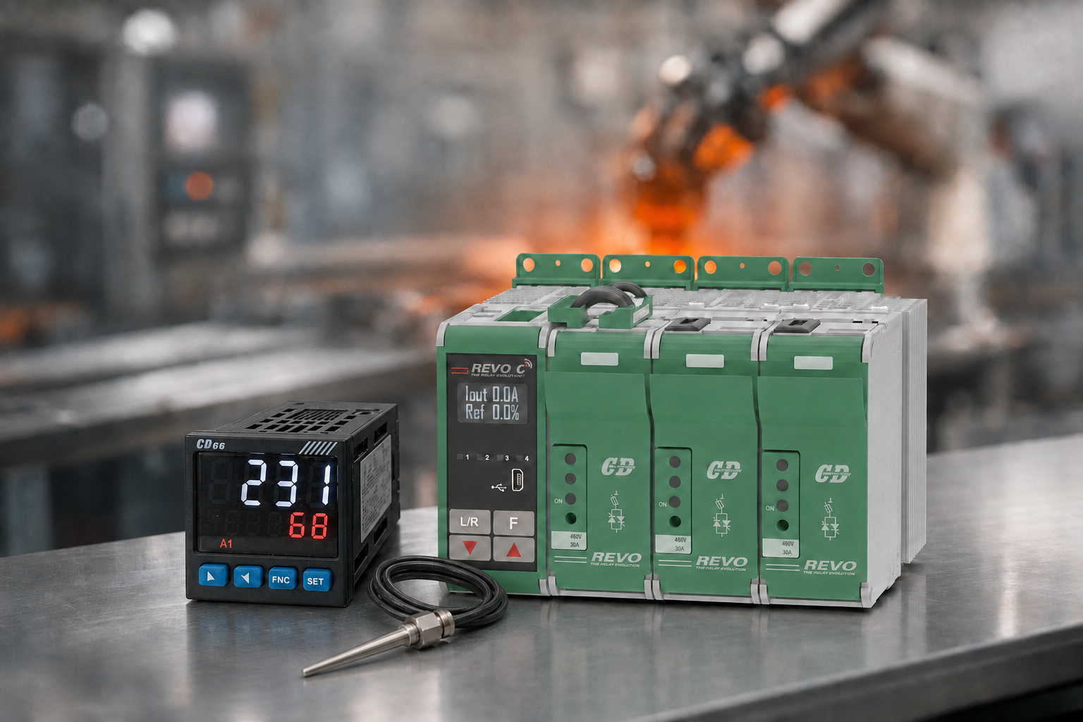
Consequently, operators may increase setpoints or extend cycle times to create a safety margin. That approach can mask the fault for a while, but it increases energy consumption and may accelerate heater wear. It also leaves the underlying control problem in place.
Accurate control matters most where the process has narrow tolerances, high material value or long warm-up periods. For example, a multi zone oven may need each zone to follow a distinct profile i.e. master/slave arrangement. Meanwhile, a single thermal treatment vessel may require tight control around one critical setpoint.
The correct requirement therefore depends on the process, not simply on the controller display. Response speed, sensor type, output method, alarm strategy and communications all affect whether the equipment can maintain production at its intended rate.
At its core, a temperature controller compares a measured process value with a target setpoint. It then changes its output to reduce the difference. Although that principle is straightforward, the way it is applied determines process stability.
First, the controller needs a dependable signal. Thermocouples are widely used for high temperature applications and fast response. Resistance temperature detectors, commonly called RTDs or Pt100 sensors, are often selected where accuracy and long term stability are the priority.
However, sensor selection is only part of the decision. Cable routing, termination quality, electrical noise and sensor position can all distort the measured value. A sensor placed too far from the heated material may report a stable temperature while the product itself remains outside tolerance.
Accordingly, engineers should consider the thermal mass, airflow, immersion depth and distance from the heating element before selecting the input configuration. A well specified controller cannot correct a measurement taken from the wrong location.
On-off control suits simple applications with generous temperature tolerance. In that arrangement, the output switches fully on below the setpoint and off above it. Hysteresis prevents rapid switching, although the process temperature will naturally cycle around the target.
By contrast, PID control continuously adjusts the output according to present error, accumulated error and the rate of change. Therefore, it can reduce overshoot and steady state variation in more demanding processes. Correctly tuned PID parameters are especially valuable for fast heaters, low thermal mass loads and applications where product quality depends on repeatable heat transfer.
Autotuning can provide a useful starting point, but it is not a substitute for commissioning under real operating conditions. Load changes, fan operation, batch size and ambient conditions can alter the thermal response. As a result, final settings should be checked against the actual process rather than a no load test.
The controller output must match the device that controls heater power. A relay output may be suitable for a small contactor operated load, while a logic, analogue or SSR drive output is commonly used with a solid state relay or thyristor power controller.
Importantly, the temperature controller is not usually intended to switch a high current industrial heater directly. It provides the control command. The power controller handles the electrical load, including the current, voltage, phase arrangement and firing method required by the application.
Specification should begin with the process requirement, then move outward to the electrical system. Too often, a replacement controller is chosen because it physically fits the panel cut-out or matches a familiar part number. That can retain the same performance limitation that caused the problem.
Instead, establish the operating range and required control accuracy. Next, identify the sensor technology, number of heating zones, required ramp and soak profiles, alarm needs and operator interface. These factors define the controller function.
Then assess the heater load. Resistive heaters, silicon carbide elements, infrared lamps and transformer coupled loads behave differently. Likewise, a single phase load requires a different power control arrangement from a three phase star or delta connected system.
Where power demand is substantial, the relationship between controller and thyristor unit needs particular attention. Burst firing may suit many resistive loads and can support efficient, stable heating. Phase angle firing may be required for some load types or finer control behaviour, although it can create greater harmonic and electromagnetic interference considerations.
Therefore, the specification should include load current, supply voltage, phase configuration, heater characteristics and the preferred firing mode. It should also account for future expansion. A panel with spare capacity and accessible terminals is easier to maintain than one designed to its absolute limit.
Communications may also be decisive. Modbus, Ethernet or other industrial protocols can allow setpoints, alarms and process values to be viewed through a PLC, HMI or supervisory system. Nevertheless, connectivity should serve a defined operational purpose, such as traceability, remote diagnosis or recipe control, rather than add complexity without value.
Temperature control performance can be undermined by panel integration. Electrical noise from variable-speed drives, poor earthing and inadequate segregation between sensor and power cables can lead to fluctuating readings or nuisance alarms. For that reason, low level sensor wiring should be routed separately from high current conductors wherever practical.
EMI power line filters may be necessary where switching devices and sensitive control electronics share an environment. Similarly, suitable fusing, circuit protection and thermal management protect both the power control equipment and the production schedule.
Panel temperature deserves attention as well. Controllers and thyristor units generate heat, while enclosed cabinets may operate near furnaces, ovens or extruders. Consequently, enclosure layout, ventilation and clearance must be assessed against the equipment ratings rather than assumed from a nominal ambient figure.
A clear fault strategy is equally important. High temperature alarms can protect product and equipment, whereas low temperature alarms can identify heater failure, supply loss or an open circuit. Independent over temperature protection may be required where a control fault could create a safety or quality risk
A controller that powers up is not necessarily commissioned. Initial testing should confirm sensor scaling, polarity, setpoint limits, alarm operation and output direction. For instance, an incorrectly configured thermocouple input can create a reading that appears plausible while moving in the wrong direction.
Afterwards, the heating system should be tested through its normal operating range. Observe warm up, overshoot, recovery after a disturbance and stability at production temperature. Record these results so that maintenance teams have a known performance baseline.
During this stage, check that the power controller responds consistently to the command signal. An output that is stable at the temperature controller but erratic at the heater points to a separate issue in the power stage, wiring or supply. Separating these faults early prevents unnecessary controller replacement.
Finally, document settings, wiring references, sensor locations and alarm limits. This reduces diagnosis time during future breakdowns and gives OEMs a repeatable build standard across machines.
Frequent manual adjustment, unexplained temperature cycling and repeated heater failures are warning signs worth investigating. Equally, an obsolete controller with limited spares can turn a minor fault into a long production interruption.
Replacement does not always mean a like-for-like swap. A revised controller and power control arrangement may improve zoning, add meaningful alarms or provide production data that was previously unavailable. Still, the case for an upgrade should be based on the load and process evidence, not features alone.
CD Automation UK approaches temperature control as part of the electrical heating system, specifying the controller, thyristor control and panel integration measures around the actual application. Before the next heating fault becomes lost output, capture the process data, load details and control symptoms needed for a proper engineering assessment.

