Inductive loads require careful power control because current and voltage do not behave in the same way as they do with a standard resistive heater.
When switching the primary side of a transformer, the thyristor controller must manage transformer magnetising current, prevent core saturation and control the power delivered to the secondary load. Incorrect setup can cause excessive current, fuse operation, electrical noise and transformer damage.
Primary-side transformer control is commonly used in:
The transformer converts the mains supply into the lower voltage and higher current required by the heating elements.
Most industrial transformer-heating applications have either a normal-resistance or variable-resistance heating element connected to the secondary.
The type of element has a major influence on how the thyristor controller must be configured.
Normal-resistance elements have a relatively stable resistance between cold and normal operating temperature.
Typical examples include:
For these loads, the main control considerations are:
Once the transformer has been energised safely, the load is generally predictable and straightforward to regulate.
Variable-resistance elements change significantly as they heat or age.
Typical examples include:
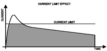
These loads require additional control functions because the secondary current can vary considerably during start-up and operation.
Depending on the element type, the thyristor setup may require:
For example, MoSi₂ elements have a very low cold resistance and require tight current limiting during start-up. Silicon carbide elements increase in resistance as they age and require sufficient voltage reserve to maintain rated power.
The transformer, heating element and thyristor controller must therefore be considered as one complete system.
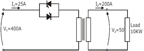
Switching the secondary of the transformer is the same as driving a standard resistive load. The issue with this solution is the size of thyristor unit can be 8 times larger than a unit to switch the primary (i.e. 25A v 200A).
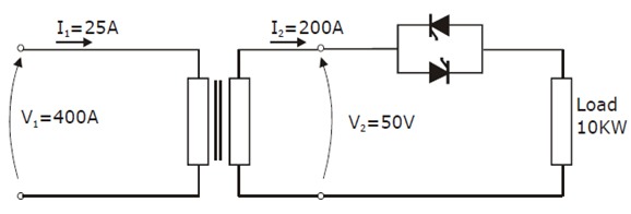
Controlling the primary side allows the thyristor controller to operate at the higher transformer input voltage and lower current.
This can provide:
However, the transformer characteristics and secondary load behaviour must both be understood before the controller is selected.
A transformer stores energy in its magnetic field and can draw a high magnetising current when energised.
Problems may occur if:
These conditions can produce severe current peaks, even when the normal running current is within the expected range.
Phase-angle firing with controlled soft start is generally the preferred method for transformer-primary control.
Phase-angle firing allows the RMS voltage to increase progressively, reducing sudden magnetising current and helping prevent core saturation.
The exact setup then depends on the secondary heating element.
The controller will typically require:
The controller may additionally require:
Correct setup protects the transformer, heating elements and upstream electrical system.
REVO C is well suited to transformer-primary applications requiring advanced firing control, current limiting and load monitoring.
Available functions include:
The final configuration should be selected to match both the transformer and the type of heating element connected to the secondary.
A transformer-primary controller cannot be selected from heater kW alone.
To specify the correct solution, we need:
CD Automation can help you assess the transformer, identify the secondary load characteristics and configure the correct firing mode, soft start and protection limits.
Speak to a Power Control Specialist
Send us the transformer nameplate data, secondary element details and electrical supply information.
Call 01323 811 100 or submit your application details today.

What happens next?
This isn't an automated product-selection tool.
One of our team will look at the information you've provided and review the application from an engineering point of view.
We may come back with a few questions, but we'll normally be looking at things such as:
No lengthy specification needed.
Just give us enough information to get the conversation started.
Prefer to talk?
Call us on 01323 811100
CD Automation UK
Industrial power control. Backed by people who understand the application.
