In an industrial AC heating controller, the firing electronics coordinate this switching with the supply waveform. By controlling when current is allowed to flow, the unit regulates the electrical power delivered to the heater.
Understanding this process helps explain what a thyristor controller can do, how it differs from a temperature controller and why the correct configuration matters.
What happens inside a thyristor?
The thyristors commonly used in AC heating power controllers are silicon controlled rectifiers, or SCRs.
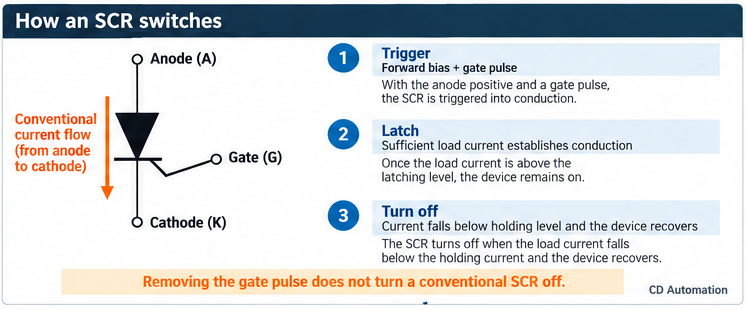
An SCR has four alternating semiconductor layers, commonly described as a PNPN structure, and three terminals: the anode, cathode and gate. The anode and cathode carry the main load current; the gate receives the triggering signal.
Its normal switching sequence has three stages.
1. The device blocks current
Within its rated operating conditions, the SCR remains in its blocking state until it receives a suitable trigger. Applying forward voltage alone is not the intended method of turning it on.
2. A gate signal starts conduction
With the anode positive relative to the cathode, a suitable gate pulse starts conduction. Once the main current has risen sufficiently to establish latching, the gate pulse can be removed and the SCR remains on.
3. Falling current allows it to turn off
The SCR cannot normally be turned off simply by removing the gate signal. Its current must fall below the level needed to sustain conduction, the holding current condition, and the device must recover its blocking capability. In AC operation, this normally occurs around the load-current zero crossing.
The important distinction is current zero, not necessarily voltage zero. With inductive loads, current can lag behind voltage, which affects the switching behaviour and the controller configuration required.
Why do AC controllers use two SCRs?
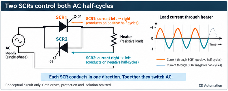
An individual SCR conducts in one direction. AC current, however, reverses direction.
A common AC power switching arrangement therefore uses two SCRs connected in inverse parallel, often described as “back-to-back”.
One carries current in one direction; the other carries it in the opposite direction. Together, they allow control of both halves of the AC waveform.
Although SCR stands for silicon controlled rectifier, this arrangement does not turn the heater supply into DC. It controls the delivery of AC power.
The same principle is used within multi phase power controllers, with the switching arrangement selected to suit the load connection and number of controlled legs.
How does a PLC or temperature controller control the heater?
The thyristors are the power switching components. The complete power controller also contains the electronics that interpret the demand signal and generate the required gate pulses.
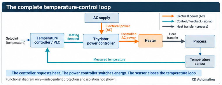
In a typical temperature control system, a sensor measures the process temperature. A temperature controller or PLC compares that measurement with the setpoint and calculates the required heating demand. The thyristor power controller then applies electrical power to the heater.
The temperature controller decides how much heating is needed; the power controller determines how electrical power is delivered.
Depending on the product and configuration, that demand may arrive as an analogue signal such as 4–20 mA or 0–10 V, an SSR drive logic signal, or a communications command. REVO C supports several input and communications arrangements, with functionality dependent on the ordered configuration.
The control signal does not supply the heater’s energy. It instructs the power controller; the heater receives its energy from the electrical power supply.
What does a 50% output command actually mean?
An output percentage only makes sense when the input scaling and control mode are known. You must distinguish between voltage, current and power control modes, so the same percentage must not automatically be interpreted as the same physical output.
Consider an illustrative system configured so that 4–20 mA represents 0–100% power demand, with no active limiting or fault condition:
12 mA corresponds to a 50% demand.
For a fixed resistance heater that draws 10 kW at the applied supply voltage, burst firing for half the available complete cycles would deliver approximately:
10 kW × 0.5 = 5 kW average power
That does not mean the controller continuously supplies half the voltage. During each conducting cycle, the load receives the supply waveform, apart from the small voltage drop across the conducting devices.
Nor does 50% power mean 50% temperature. The resulting temperature depends on the process, heat losses, thermal mass and operating conditions, not just the demand percentage.
How does firing timing regulate power?
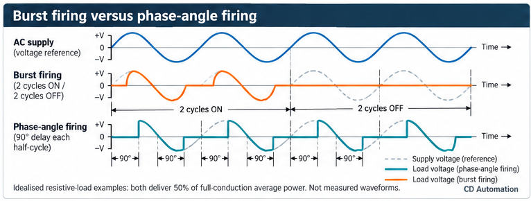
The method used to schedule SCR conduction is called the firing mode. Two widely used approaches are burst firing and phase angle firing.
Burst firing: controlling complete cycles
Burst firing regulates average power by allowing some complete AC cycles through and withholding others. Changing the proportion of conducting cycles changes the average energy delivered to the load.
For example, more conducting cycles produce more average heater power; fewer conducting cycles produce less. The exact cycle pattern depends on the controller’s settings and firing algorithm.
Zero cross switching and burst firing describe related but different aspects of operation. Zero cross identifies when switching is initiated relative to the waveform; burst firing describes how conducting cycles are scheduled to regulate power.
Thyristor switching in practice: McLaren’s paint drying system
When a specialist paint finish caused drying delays at McLaren, Panther Engineering designed a bespoke heating solution incorporating three CD Automation REVO S thyristor power controllers. These used burst firing to regulate power to resistive heaters. By switching complete AC cycles on and off, the controllers varied the average electrical power delivered to the heaters, putting the switching principle explained above into practice in an automotive production environment.
Read the McLaren and Panther Engineering paint drying case study
Phase angle firing: controlling part of each half cycle
Phase angle firing delays the SCR trigger within each half cycle. For a resistive load, triggering earlier gives a longer conduction period and more power; triggering later gives a shorter conduction period and less power.
This approach provides control within individual half cycles, but the output is a chopped waveform, not a smaller, undistorted sine wave. It also has different electrical interference implications from whole cycle switching.
The choice is application dependent. For detailed guidance on matching firing methods to resistive heaters, infrared lamps and transformer fed loads, see why firing mode selection matters in industrial heating.
What is the difference between firing mode and feedback?
Firing mode determines when the SCRs conduct. Feedback determines which electrical quantity the controller is trying to regulate.
A controller using electrical feedback measures the relevant output and adjusts its firing to respond to the demand. Depending on the model and configuration, this may involve voltage, current or power regulation.
For example, a power control configuration can adjust its output as electrical conditions change, within the available supply and configured limits. This is different from simply repeating a fixed switching pattern without checking the resulting electrical output.
Electrical feedback also remains distinct from temperature feedback. A heater can receive the requested electrical power while the process temperature is wrong because of a sensor issue, heat loss or another process condition. Reliable heating therefore depends on the complete control system, not the power controller alone.
Why use thyristors rather than mechanical switching contacts?
Thyristors switch electronically, so there are no power switching contacts to open, close or erode. This makes semiconductor switching suitable for frequent operation without the contact wear associated with mechanical switching.
For heating applications, shorter and more closely controlled power cycles can reduce temperature excursions compared with a system using long on/off periods. The practical benefit depends on the heater, firing method and thermal response of the process.
However, solid state switching is not the same as a maintenance free system. Cooling and protection remain important, and changing the power controller does not automatically correct poor temperature sensing or unsuitable control settings.
Is a thyristor the same as a solid-state relay?
Not exactly.
A thyristor or SCR is a semiconductor component. A solid state relay, or SSR, is an assembled switching device that uses semiconductor components rather than mechanical contacts. An AC SSR may contain SCRs or another suitable switching technology, such as a triac.
A thyristor power controller combines the power switching devices with control electronics. Depending on the product, it may also provide configurable firing modes, electrical feedback, current limiting, measurements, alarms and communications.
These categories overlap. The useful question is not simply “SSR or thyristor?” but which switching and control functions does the application need?
Why do thyristor controllers need heatsinks?
A conducting semiconductor has an on-state voltage drop, so some electrical energy is dissipated as heat inside the controller. A heatsink, and, on some models, fan cooling, removes that heat.
The lack of mechanical contacts does not mean the unit runs cold. Cooling arrangements must suit the selected rating and installation conditions.
For the current calculations and derating checks involved, see how to size a thyristor power controller.
Does “off” mean the heater circuit is safely isolated?
No. A zero demand command is not electrical isolation.
Solid state controllers can have off state leakage, and semiconductor devices can fail short circuit. Appropriate isolation and fault shutdown arrangements must therefore be provided as part of the electrical design. Where uncontrolled heating presents a risk, the protection strategy must not rely solely on the normal control signal.
This distinction matters both for machine safety and for maintenance: “not currently heating” does not establish that a circuit is safe to work on.
Applying thyristor control to your process
The switching principle is straightforward. Applying it reliably requires the controller to match the heater, supply, control system and operating environment.
CD Automation supports application specific configuration and retrofit assessment, helping customers establish the appropriate power control arrangement rather than selecting on current rating alone.
To discuss a new machine or an existing installation, provide the process description, heater type, supply voltage, phase arrangement and load per zone. Include the control signal, required diagnostics, cabinet conditions and any special requirements.
For project planning, also include quantities, delivery location and whether commissioning or design support is needed.
Call CD Automation on 01323 811100 to discuss your heating application.
View our Thyristor Controller range to see all our product offerings.