A thyristor power controller can regulate a high power heating loads with excellent precision, but its switching action can also introduce electrical noise onto the supply. EMI & RFO power filters are the engineered control point for that risk. Correctly specified, they help protect sensitive equipment, support compliance and prevent a power control panel from becoming the source of faults that are difficult to trace.
For manufacturing teams, this is not simply a matter of passing an EMC test.
Conducted interference can affect communications, instrumentation, PLC inputs, sensors and neighbouring drives. The operational result may be intermittent alarms, unexplained resets, unstable readings or lost production time. These faults are especially costly because they often appear only under particular load conditions or firing modes.
Electromagnetic interference, or EMI, is unwanted electrical energy that can travel through cables (EMI) or radiate from equipment (RFI). In electrically heated process equipment, the most significant concern is often conducted EMI: high frequency noise carried back along the mains supply and into other connected equipment.
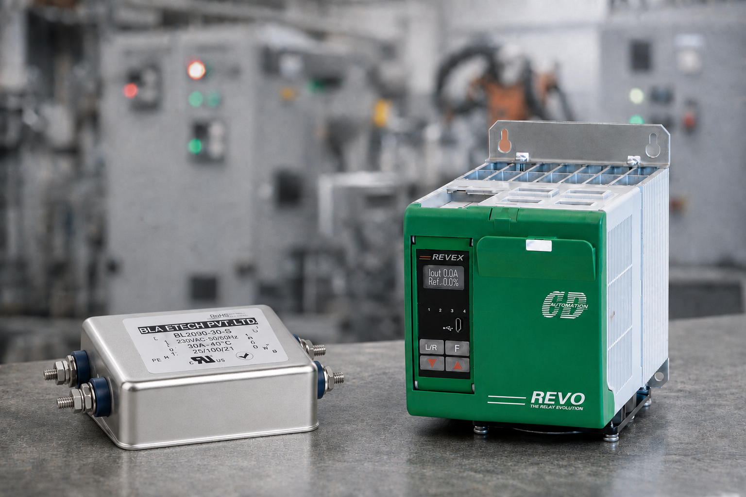
Phase angle fired SCR and thyristor controllers are a common source because they switch part way through the AC waveform to vary the energy delivered to the load. This gives responsive, precise temperature control for applications such as furnaces, extruders, dryers, ovens and moulding machinery. The trade off is rapid voltage and current change at the switching point, which can generate harmonics and high frequency disturbance.
Burst firing, also called time-proportioned zero cross firing, normally produces lower levels of high frequency interference because switching occurs at, or close to, the zero crossing of the waveform. However, it is not a universal substitute for phase angle control. Some loads and processes require the finer response offered by phase angle operation, particularly where thermal dynamics are fast or precise power modulation is necessary. Filter selection must therefore follow the application, not a blanket preference for one firing mode.
An appropriately selected filter attenuates unwanted high frequency noise before it reaches the wider electrical installation. This helps maintain the intended performance of control equipment and supports electromagnetic compatibility requirements for the finished machine or panel.
A panel may appear to operate correctly during basic commissioning but develop intermittent problems once it is installed alongside real production equipment. A nearby temperature controller may display an unstable signal. A communications network may drop out when a large heater bank ramps up. An RCD may nuisance trip. A PLC may record an input fault with no obvious field device failure.
Not every one of these issues is caused by EMI, and a filter cannot correct poor earthing, damaged cable insulation or an incorrectly designed control circuit. But omitting, undersizing or incorrectly installing a filter removes an important layer of control from a system that contains switching power electronics.
There is also a compliance consideration. The machinery or control panel manufacturer is responsible for the EMC performance of the completed assembly, not merely the individual controller. A controller may have documented emissions characteristics, but those results depend on defined test arrangements, supply conditions, wiring practices and compatible filtering. Changing cable routing, enclosure construction or load configuration can change the installed result.
For OEMs, this matters at design stage. For plant teams upgrading a legacy heater control panel, it matters before the first production run. Retrofitting after a fault investigation is possible, but it is usually slower and more disruptive than specifying the correct arrangement from the outset.
An EMI filter should never be chosen on current rating alone. The filter has to suit the electrical architecture, the controller’s operating behaviour and the environment in which the panel will run.
Start with the supply. Is the system single phase or three phase? Is a neutral present? Is the load balanced across phases, or are separate single phase circuits being controlled? The filter configuration must match the supply arrangement and the way the controller is connected.
Current rating needs practical headroom. Consider the controller rating, continuous load current, diversity between zones and foreseeable process changes. A filter operating close to its thermal limit can run hot and have a reduced service life. Equally, fitting an unnecessarily large device without reviewing leakage current, physical layout and protection coordination can create a different set of problems.
The voltage rating and operating frequency must also match the installation. UK industrial systems commonly operate at 400/415V three phase, but machinery may include other supply arrangements. The filter specification should reflect actual line-to-line and line-to-neutral conditions rather than assumptions made from a nominal plant supply.
The electrical behaviour of the load affects the filtering requirement. Resistive heaters are generally straightforward, yet their arrangement still matters. A multi zone oven with independent phase angle controllers presents a different emissions profile from a single high current furnace using burst firing.
Infrared lamps, silicon carbide elements, molybdenum disilicide heaters and transformer-coupled loads all require closer review. Their resistance can change significantly with temperature, and transformer loads introduce inductance and inrush considerations. Where a controller is operating in phase angle mode, the chosen filter and any associated line reactor should be assessed as part of the complete power circuit.
A useful rule is simple: specify the filter against the controller and load combination at its most demanding normal operating condition. Do not base the decision solely on a low average process power figure when the system experiences high peak current or frequent modulation.
EMI filters use capacitive components to divert high frequency noise away from the supply conductors. That design can introduce earth leakage current. In installations protected by RCDs, the cumulative leakage from filters, drives, switch mode power supplies and other electronic equipment must be considered.
This does not mean filters should be avoided. It means the protection strategy needs engineering attention. The type, rating and location of RCDs, plus the filter’s leakage characteristics and the panel earthing arrangement, should be reviewed together. A nuisance trip that stops an oven line or extrusion process is not an acceptable maintenance burden.
A quality filter installed poorly can deliver disappointing results. The objective is to stop noise coupling around the filter through wiring, enclosure surfaces or shared cable routes.
Mount the filter close to the incoming supply point for the controlled equipment, using a low impedance earth connection to the panel backplate. A broad, short earth bond is preferable to a long, thin conductor, which has greater impedance at high frequency. The mounting surface should provide sound metal-to-metal contact where the design requires it, with paint removed as appropriate and corrosion protection managed correctly.
Keep the unfiltered supply side conductors physically separated from the filtered load side conductors. If they run alongside each other for an extended distance, noise can couple from one side to the other and bypass much of the filter’s benefit. Avoid unnecessary loops, keep cable lengths short and route control cables away from high current switching conductors.
Screened signal cable, correct screen termination and sensible segregation remain necessary. EMI filtering is one part of a coordinated EMC design, alongside earthing, bonding, enclosure layout, cable routing, surge protection and sound control circuit practice.
When assessing filtering for a new panel or upgrade, gather the information that determines real electrical behaviour:
Include details of nearby sensitive equipment, communications systems and any historic nuisance trips.
From there, assess the controller manufacturer’s installation guidance and the expected emissions environment. A small standalone machine may have different constraints from a multi zone production line with several high current controllers operating from a shared incomer. There is no benefit in treating both as the same application.
CD Automation applies this application led approach when specifying power control systems. The filter, controller, protection and panel layout should operate as one engineered solution, not as a collection of individually compliant components.
If interference appears after installation, resist the temptation to fit a larger filter without investigation. Check earth continuity and bonding first, then inspect routing, controller parameters, switching mode, snubber arrangements and the condition of power and control cables. Confirm whether the disturbance is conducted through the supply, coupled into a signal cable or caused by another source entirely.
Measurement is valuable where the problem is persistent or production critical. Capturing when faults occur relative to heater switching, load changes or other equipment operation can narrow the cause quickly. An intermittent PLC reset during high-power demand tells a different story from a communications fault that occurs only when a variable speed drive starts.
The most dependable result comes from considering EMI at the same point as power-control selection. When the supply, load, firing strategy, filter and panel layout are aligned before commissioning, the heating process has a far better chance of delivering stable output without creating avoidable disruption elsewhere on the line.

