A reliable furnace does more than reach its target temperature. It starts predictably, maintains the conditions the process needs and responds safely when something goes wrong. Getting these fundamentals right helps protect product quality and avoid unnecessary production interruptions.
For furnaces using molybdenum disilicide, usually written as MoSi₂, good control begins with understanding how the heating elements behave. Once that is clear, the decisions about power control, temperature measurement and protection become much easier to follow.
The most important electrical characteristic of a MoSi₂ element is its change in resistance as it heats up.
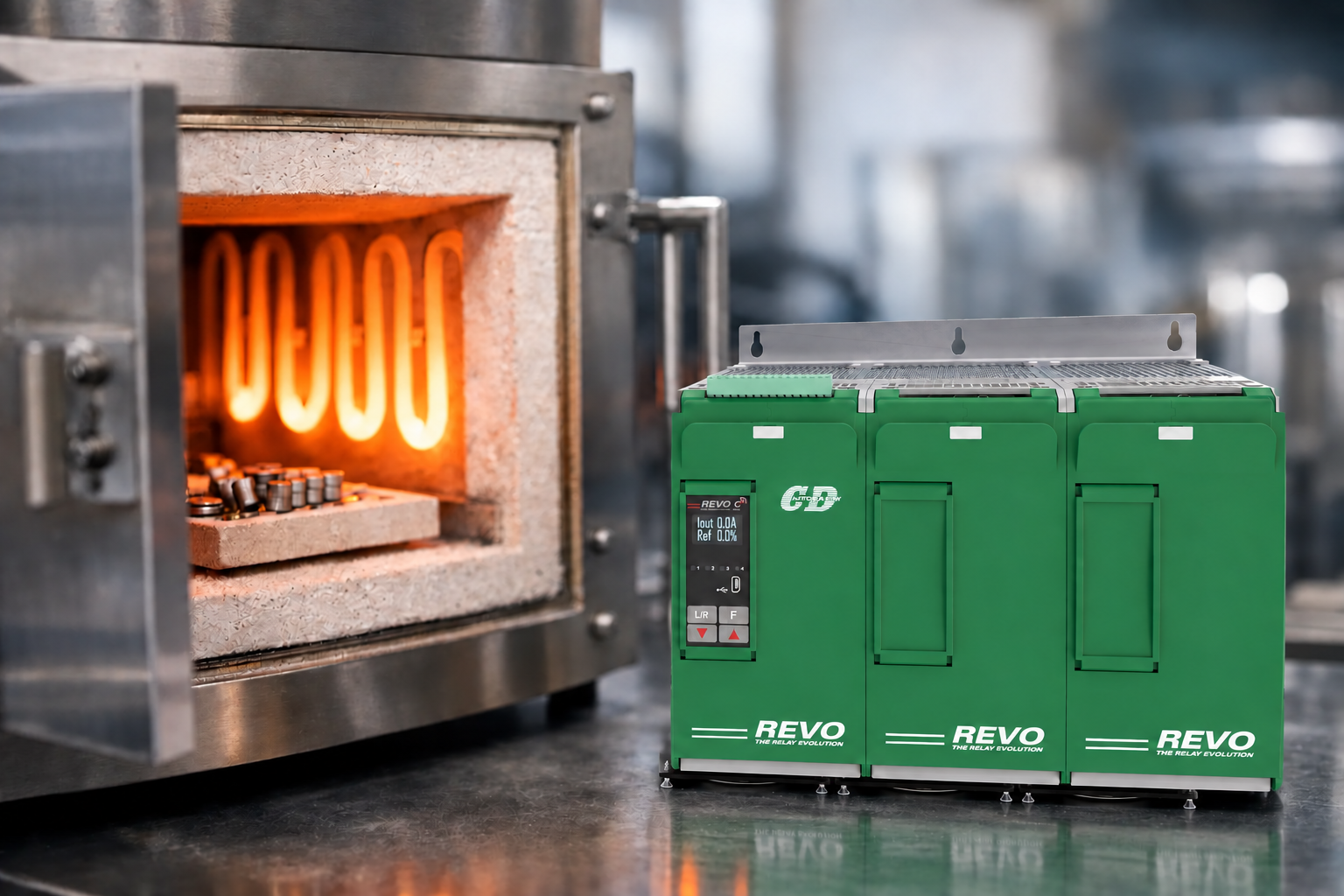
The REVO-C is an ideal power controller for controlling MoSi₂ elements
The most important electrical characteristic of a MoSi₂ element is its change in resistance as it heats up.
When the element is cold, its resistance is low. At a given voltage, that allows more current to flow than when the element is hot. Applying the normal operating voltage directly to cold elements can therefore produce excessive current. The power control system needs to manage this part of the heating cycle, rather than being selected only for normal running conditions.
There is a useful distinction here: resistance changes with temperature, but MoSi₂ elements generally maintain comparatively stable resistance as they age, when compared at the same temperature. Correctly specified new elements can often work alongside existing ones, although replacements must still meet the element manufacturer’s requirements.
The practical takeaway is straightforward: design for both cold start and normal operation, not just the point at which the furnace is already hot.
Before choosing a power controller, establish what it will actually be controlling.
Start with the supply voltage, phase arrangement, power required by each heating zone and the way the elements are connected. Add the element manufacturer’s operating data, particularly the cold resistance and permissible current. Where a transformer is fitted, its rating and connection also form part of the specification. A total furnace power figure alone does not provide enough information to make a dependable selection.
The installation matters too. A controller operating inside a warm, crowded enclosure faces different conditions from one installed in a well-ventilated panel. Its rating, mounting arrangement and cooling requirements must suit the conditions it will experience in service.
This is the basis of CD Automation’s application led approach: understand the load and installation first, then select the controller and configuration to suit them.
It helps to separate two functions that are closely linked but do different jobs.
The temperature controller compares the measured temperature with the target and determines how much heating is required. The power controller regulates the electricity delivered to the elements in response to that demand. Both functions need to work together, but temperature control alone does not provide all the electrical management the load requires.
For MoSi₂ elements, phase angle control with electrical soft start and suitable current limiting is an established way to manage cold start. Soft start increases the output progressively, while current limiting keeps the electrical demand within the specified limit. The settings must suit the actual element circuit.
The term phase angle control describes a method of applying only part of each alternating current supply cycle to the load. This allows the controller to regulate the voltage applied to the elements.
Burst firing controls average power by switching complete supply cycles on and off. However, switching on for less time does not, by itself, reduce the current flowing during each energised cycle. Cold elements can therefore draw excessive current even when the average output is relatively low.
This is why plain zero cross burst firing should not be chosen for MoSi₂ start-up. Depending on the installation, the controller may remain in phase angle operation or transfer to another suitable firing mode once the elements have warmed sufficiently. The transition must be appropriate for the load and any transformer involved.
A programmed temperature ramp is also different from an electrical soft start. The ramp sets how quickly the requested furnace temperature rises; it does not, on its own, establish a safe limit for element current. The heating programme and electrical limits should be selected together, following the furnace and element manufacturers’ guidance.
Where a transformer supplies the elements, there are two separate start-up issues to address.
The first is the current drawn by the cold elements. The second is the transformer’s own brief surge of current when it is energised. A method that addresses one should not be assumed to solve the other. In particular, switching a transformer primary at the supply voltage’s zero crossing can produce substantial inrush rather than minimise it.
The specification should therefore identify whether the controller switches the supply side or the element side of the transformer. The firing method, start-up settings and restart behaviour can then be assessed for that complete arrangement. This is another reason to review the circuit before selecting a controller from its current rating alone.
Once the electrical start-up is under control, attention turns to the temperature measurement.
A controller responds to the temperature its sensor reports. A thermocouple positioned too close to an element may indicate that the target has been reached while the product is still heating. Equally, a sensor in an unrepresentative part of the furnace may lead to unnecessary power adjustments. Sensor position should therefore be considered alongside the product loading, heating zone layout and furnace construction.
A steady number on the display is useful, but it is not proof that the whole load has reached the required temperature.
The control settings also need to suit the furnace’s response. Often called PID tuning, these settings determine how the controller adjusts its output as the measured temperature approaches or moves away from the target. Suitable tuning helps avoid repeated temperature swings, excessive overshoot and slow recovery after a disturbance such as a door opening.
The aim is not simply to make the controller respond quickly. It is to make it respond appropriately for the furnace and the process.
Good control manages normal operation. Protection must also deal with abnormal conditions and component failures.
Electrical protection needs to be coordinated across the installation. Suitable semiconductor fuses help protect the power electronics from short circuit fault energy, while the wider design must also provide appropriate cable protection and maintenance isolation. These functions should be considered together rather than treated as interchangeable.
Over temperature protection has a separate role. An independent limiter, with an appropriately independent sensing arrangement, should be able to stop heating if normal temperature control fails. Crucially, the shutdown must not rely solely on an “off” command to the same semiconductor power controller. Semiconductor switches can fail short-circuit and continue supplying the load, so an appropriately rated independent device, such as a contactor, is needed to interrupt heating power.
The principle is simple: the system that protects against overheating must remain effective when the normal power control path fails.
Commissioning is where the electrical design and the heating process are checked together.
An empty furnace trial is useful, but the final assessment should also reflect normal product loading and site conditions. Record current during cold start, heat-up and steady operation, and compare it with the agreed limits. Where the controller changes firing mode, check that transition and confirm that the furnace restarts correctly after a shutdown.
Temperature checks should show whether each zone reaches and holds its target without unacceptable overshoot, repeated fluctuations or excessive delay. The commissioning procedure should also verify alarms and the independent over temperature shutdown, including confirmation that a protective trip actually removes heating power.
Where load failure monitoring (heater break alarm) is included, establish what it is expected to detect in the installed element arrangement and test that behaviour. Treat an alarm as useful diagnostic information, rather than assuming it will always identify the exact failed component.
Commissioning records provide a useful reference when performance changes later. Record measured current and electrical power alongside temperature behaviour, and compare equivalent recipes and loading conditions.
Keep the controller’s output demand separate from measured power. An output percentage is a command whose meaning depends on the configured control mode; it is not automatically a direct measurement of the electrical power being delivered.
This distinction makes fault finding more focused. Rather than assuming that a higher output demand means ageing elements, investigate what has changed in the loading, heat losses, measurements or electrical circuit.
The starting point for dependable MoSi₂ furnace control is a clear understanding of the application. The controller then becomes part of a coordinated design, alongside the elements, transformer, temperature measurement and protection.
At CD Automation, we help customers assess the load connection and choose a power control approach suited to their MoSi₂ application. That means looking beyond the headline current rating to the start-up behaviour and operating requirements that determine whether the selection is appropriate.
For a new furnace, bring those questions into the design discussion early. For an existing installation, use the circuit drawings, element data and operating records to make the review specific: when do trips occur, which zones recover slowly, and what happens during cold start?
Discuss your furnace application with CD Automation. Start with the supply details, power per zone, element specification and any transformer information, together with the performance you need to achieve. These provide the foundation for an engineering discussion about the complete heating system, not simply a replacement part number.
Power control reliability depends on the complete electrical path. A correctly rated controller can still fail prematurely if it sits in a hot enclosure with restricted airflow or is fed through undersized terminals.
Review the following items as part of the heater load calculation:
Moreover, consider diversity only when it is real and controlled. Several heating zones may not all run at full output during steady production, but they often do during heat up. Designing the incoming supply around an assumed diversity factor can create nuisance trips precisely when the machine needs maximum power.

