A relay that fails closed can turn a straightforward maintenance task into overheated product, damaged tooling and a stopped line. That is why solid state relays should be specified as part of the complete heating circuit, not selected from a current-rating table alone.
The correct device, heatsink, protection and control method help maintain stable temperatures and keep electrically heated production equipment available when output matters most.
A solid state relay (SSR) uses semiconductor devices rather than moving contacts to switch power to a load. For industrial heating, it is commonly used to switch single phase resistive heater circuits in response to a low voltage control signal from a temperature controller, PLC or process controller.
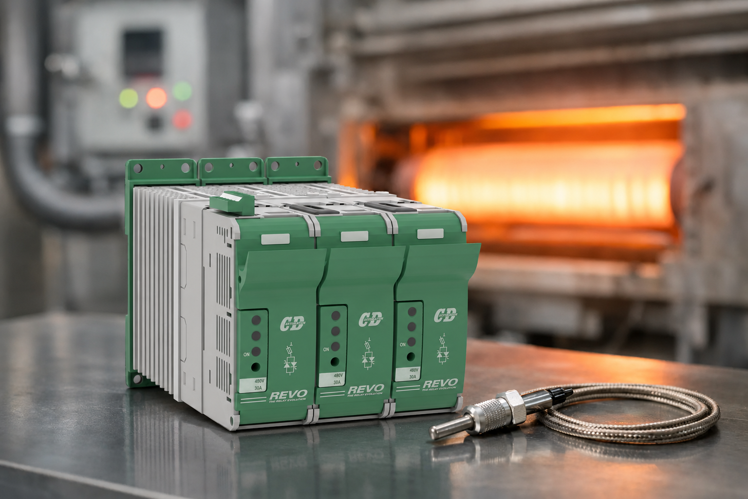
With no mechanical contacts to arc or wear, an SSR can switch frequently and quietly. This makes it well suited to time proportioning temperature control, where heater power is applied in short, repeated cycles to hold a process close to setpoint. It can improve control stability compared with a contactor that is asked to cycle more often than it was designed to.
That advantage does not make every application a simple SSR replacement. A contactor provides visible isolation and has different failure behaviour. An SSR produces heat in operation, needs appropriate thermal management and may fail short circuit following severe electrical stress. A well-engineered panel may use both: the SSR for regular control and a suitably rated contactor or isolator for safety isolation and lock off.
The printed current rating is a starting point, not the final answer. Establish the supply voltage, heater resistance, normal current, operating duty and ambient conditions inside the panel. For a resistive load, current can be calculated from power divided by voltage, but the result must then be assessed against the installation conditions.
A heater circuit drawing 25A in a cool test environment may demand a significantly more capable arrangement in a crowded enclosure at elevated ambient temperature. The SSR's output voltage rating must comfortably cover the supply, including expected network variation and transient exposure. Its input must also match the available control signal, whether that is DC from a controller or PLC, or an AC control supply.
Current margin is essential, but oversizing the relay alone is not a cure for poor design. The selected device must be able to dissipate its switching losses through the chosen heatsink and enclosure arrangement. The complete assembly determines the available output current.
For many resistive heating zones, zero cross switching is the practical choice. It turns the load on as the AC waveform passes through zero, reducing electrical noise and limiting the disturbance associated with switching at other points on the wave. When paired with a temperature controller using time proportioning output, it provides dependable control for ovens, dryers, moulding machines, packaging equipment and many process heaters.
Random turn on SSRs switch as soon as the input signal is applied. They are appropriate where timing within the AC cycle is required, but they can create more electromagnetic interference when used without a clear application need. They should not be chosen simply because they appear more responsive.
Where precise, continuously variable power control is needed, particularly on larger loads or processes sensitive to thermal change, a thyristor power controller may be the better engineering choice. Phase angle or burst firing control can provide functions beyond a simple on/off SSR, including advanced diagnostics, current limiting options and multi zone integration. The right choice depends on load size, control requirement, supply constraints and the cost of process variation.
Every SSR has an on state voltage drop. At operating current, that drop becomes heat, and the heat must leave the semiconductor junction effectively. Ignore this point and a relay that looks generously rated on paper can operate at excessive temperature, derate heavily or fail prematurely.
Mount the SSR to a correctly sized heatsink using the specified thermal interface material and mounting torque. The heatsink must have sufficient airflow and clearance, and the enclosure must be assessed at realistic ambient temperatures. Positioning several heat generating devices tightly together can create a local hot spot that no catalogue rating captures.
Derating curves should be treated as design data, not small print. Review them against the actual ambient temperature, the expected continuous current and the proposed heatsink. If the panel also contains drives, transformers, power supplies or other controllers, account for their combined heat load. A cooler running SSR is not merely a longer lasting component, it reduces the risk of an avoidable production interruption.
Protection also matters. Semiconductor fuses or coordinated protective devices can limit damage when a downstream fault occurs, but the protection must be selected for the prospective fault current and the relay's characteristics. Standard circuit protection may protect cables while reacting too slowly to protect the semiconductor. This is an application specific decision, particularly where multiple heater branches, high available fault levels or critical production equipment are involved.
Most heating elements are predominantly resistive once at temperature, but their cold resistance and inrush characteristics can vary. Infrared lamps, tungsten elements, silicon carbide heaters and molybdenum disilicide heaters can have substantial cold current behaviour or resistance changes across their operating range. A relay sized only for nominal hot current may be exposed to stresses it was never intended to handle.
Transformer coupled loads, inductive devices and mixed loads need additional care. Their current waveform, switching transients and power factor differ from a straightforward resistance heater. SSR selection may still be possible, but it requires correct output type, protection and, in some cases, a different switching solution.
For three phase heating, establish whether the load is star or delta connected, balanced or unbalanced, and whether each phase must be controlled independently. A three phase SSR can simplify panel construction for suitable applications, while individual single phase devices may offer useful serviceability or zoning flexibility. Neither arrangement is automatically superior. The decision should reflect the fault strategy, spare-parts approach, wiring layout and control architecture.
An SSR is one part of a reliable power control system. The surrounding components determine whether faults are contained, diagnosed and resolved quickly. Provide clear terminal identification, appropriately rated conductors, shrouding where required, earthing arrangements and physical separation between power and control wiring. Keep sensitive analogue and communication cables away from high current switching paths.
Because SSRs can exhibit a small off state leakage current, confirm that connected loads and monitoring devices behave correctly when the relay is commanded off. This is particularly relevant for small loads, indicator circuits and some electronic equipment. Do not rely on the SSR alone as a means of safe electrical isolation.
A practical design also considers how a maintenance engineer will find a fault at 2am. Status indication, accessible test points, documented circuit drawings and correctly coordinated protective devices reduce diagnosis time. Where a failed on heater would create a safety or quality risk, independent over temperature protection and an appropriately designed shutdown path are essential.
Commissioning should verify more than whether the heater warms up. Confirm the control polarity and switching action, then measure load current under normal operating conditions. Check heatsink and enclosure temperatures after the system has reached thermal equilibrium, not just during the first few minutes of operation.
Observe temperature stability at the process, particularly where sensor position, heater response and product mass create lag. If the controller cycle time is too long, the process may oscillate even though the SSR is switching correctly. If it is unnecessarily short, the control system may create excess switching activity without improving product quality. Set the control strategy around the thermal behaviour of the equipment.
Record baseline current, temperature and panel conditions. Those readings give maintenance teams a useful reference when a heater ages, a connection loosens or process performance changes. CD Automation UK applies this load led approach to help manufacturers specify heating power control that performs predictably in the field, rather than only on a datasheet.
Solid state relays can provide dependable, fast cycling control for industrial heating, but only when electrical rating, thermal design, protection and process requirements are considered together. The cost of that engineering effort is small beside a lost batch, an unplanned shutdown or repeated replacement of incorrectly specified components.
Before approving the next heating panel design, test the selection against the real operating environment: maximum current, cold load behaviour, ambient temperature, fault level, control method and the consequence of failure. That is where reliable power control begins.

